
Dr Carlos Ziebert, Head of IAM-AWP’s Calorimeter Center, KIT, explains how the safety of stationary battery storage for renewables can be increased by battery calorimetry
System losses valued at over $32 million USD have been resulting from the 23 fires in large-scale stationary energy storage fires that have been reported in South Korea since August 2017. Therefore an in-depth study has been performed by their fire investigation committee. They found out that lack of protections against shocks, faulty installation practices and incompatibility of control systems were some of the root causes. However, also the common severe load profile which charges the Lithium-ion batteries (LIB) from close to 0% state-of-charge (SOC) to 100 % and then discharges it again in the same range on a daily basis has made the cells suffering from a high-stress level and accelerated ageing. This is common for stationary battery storage systems coupled to wind and solar farms (s. Fig.1), which produce highly fluctuating renewable energy that needs to be shifted to higher demand periods. In addition, such storage systems provide different grid services, such as peak shifting, peak shaving or frequency control and can improve overall power system efficiency and grid stability. Solar batteries are the most common small-scale battery-based stationary storage systems. These are photovoltaic systems on the roof of family houses coupled to a battery storage in the basement, garage or living room that allow storing surplus solar power for later use.
Therefore, safety and ageing tests are becoming more and more important in order to develop improved safety strategies and safety systems.
Thermal propagation studies in battery calorimeters
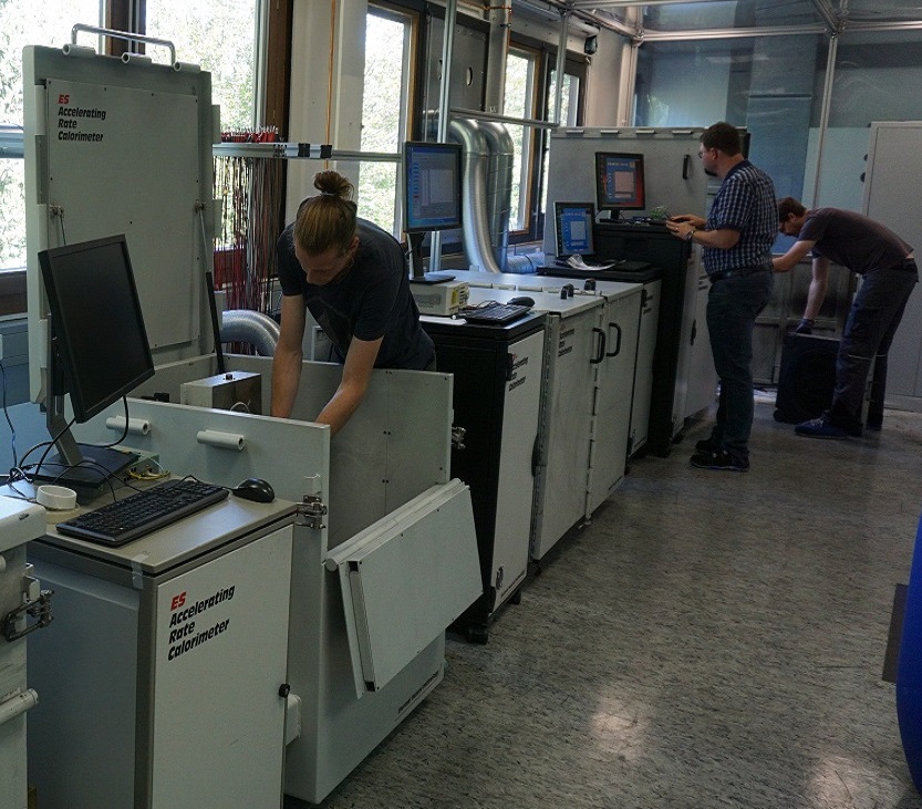
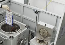
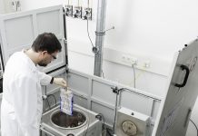
Safety testing is one of the main activities in the IAM-AWP Calorimeter Center that currently operates Europe’s largest Battery Calorimeter Laboratory with six Accelerating Rate Calorimeters (ARCs) of different sizes – from coin to large pouch or prismatic automotive format (Fig. 2). These battery calorimeters allow the evaluation of thermodynamic, thermal and safety data for LIB on cell and pack for both normal and abuse conditions (thermal, electrical, mechanical).
The chances of an individual cell failing and starting a fire is extremely small with 1 in several million. However, large stationary storage systems can have 10 million or more lithium-ion cells confined into a small space. If one cell out of these goes into thermal runaway and the implemented safety measures are not adequate, a cascading effect called thermal propagation will start a large-scale fire. This means that the thermal runaway propagates from one cell to the neighbouring cells, eventually leading to the complete destruction of the module or pack, as can be seen in Figure 3.
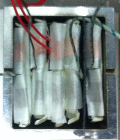
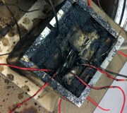
An important and adequate safety measure is heat protection barriers between cells to prevent the flames from spreading and delay the heat transfer. The largest ARCs allow studying the thermal runaway propagation in small battery packs using the setup shown in Figure 3a). It consists of a metal box with a lid, mimicking a battery box with the aim to develop and qualify suitable heat protection barriers. In order to initiate a single cell thermal runaway by overheating a heater mat is attached to one of the cells. The heat protection barrier material to be tested is installed in front of the last cell to the right and the time is measured until the thermal propagation reaches the last cell. In our laboratory, many different material approaches have already been tested with the aim to find the best solution for a certain application and cell type. Figure 3b) demonstrates a typical example for a destroyed battery pack after a thermal propagation test with an unsuited heat protection barrier.
Please note: This is a commercial profile
Contributor Details

More About Stakeholder
-
 The Calorimeter Center – Advanced Materials and Batteries
The Calorimeter Center uses calorimeters to advance thermal management and safety of batteries, handling thermodynamic, thermal and safety data.


 while also saving energy")


