Discover how researchers are making the PETRA III Swedish Materials Science beamline’s X-rays accessible for tracking the evolution of material properties during laser processing
The business model of Swedish manufacturing companies is increasingly dependent on guaranteeing the performance of complex products, which are composed of advanced materials and manufactured to exacting standards. To guarantee product performance and avoid costly or dangerous failures, manufacturers have rigorous quality control (QC) systems. QC systems involve testing components and their materials. Destructive testing methods have been traditionally used; for example, to assess weld seams, a section of the component around the weld is cut out, ground and polished, then examined using microscopy techniques. Such destructive testing methods, however, only look at the surface; they can’t look within the material or weld. Furthermore, destructive testing only gives an indication of quality – and doesn’t say if the actual product shipped to a specific customer will perform or not. Non-destructive QC methods, such as X-ray imaging, are therefore now increasingly used to guarantee the performance of a specific product shipped to a customer, providing a competitive edge.
X-ray measurement methods are also used by academic researchers in so-called ‘Big Science’ facilities. One of these facilities is the Swedish Materials Science beamline at the PETRA III synchrotron in Hamburg, Germany. This Swedish beamline was purpose-designed for measurements deep inside metallic materials, also when the material is being produced, manufactured or used. There is therefore scope to merge Big Science with QC. That way, QC approaches can include scientific assessments of the root cause of defects as well as provide input for optimizing manufacturing processes. This, however, requires making Big Science facilities such as the Swedish Materials Science beamline more accessible to new types of users from industry, e.g., via support and training, as well as by providing industrially relevant test facilities.
Such accessibility is one of the aims of the Swedish Research Council. Thanks to one of their grants, we have been able to procure and commission a continuous wave manufacturing laser at the Swedish Materials Science beamline. Our commissioning work has two aims. Firstly, to enable advanced scientific and practical research into materials and manufacturing processes during laser processing and cooling processes. That way, information such as material phases and phase size, phase transformations, residual stress, etc., as well as images of crack initiation and propagation can be captured and assessed. An important second aim is to make the laser system and instrument setup easy to use by people who are unfamiliar with Big Science synchrotron facilities. That is, make Big Science accessible, e.g., for QC engineers.
Laser system and setup
The installed laser system is equivalent to those used in manufacturing. The laser system comprises a 4kW diode laser with an output into a 600μm fiber. An alternative output is to convert the diode to a 2kW fed in to a 200μm active fiber.
Additionally, to provide flexibility in the range of industrially relevant experimental parameters, a laser optic is available with a movable collimator. This focuses the laser to spot diameters from 1.1mm to 3.5mm at a focal distance of 250mm (Fig. 2). Optionally, a powder nozzle for Directed Energy Deposition processing is in place. Smaller laser spots, for example, for welding applications, are possible using the 200μm fiber. A programmable moving axle was installed, enabling rapid movement of the specimen during X-ray observations.
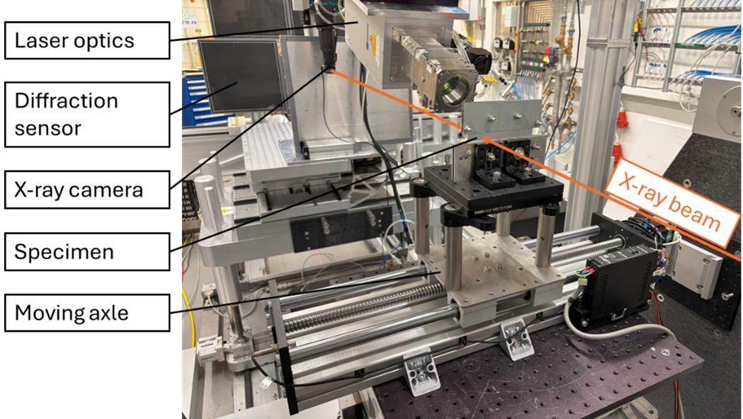
This setup enables in-situ phase formation and strain measurements as well as melt pool and solidification observations. Different X-ray detectors for diffraction and radiography (X-ray camera) are available.
Laser welding for radiographic (image) analysis
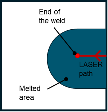
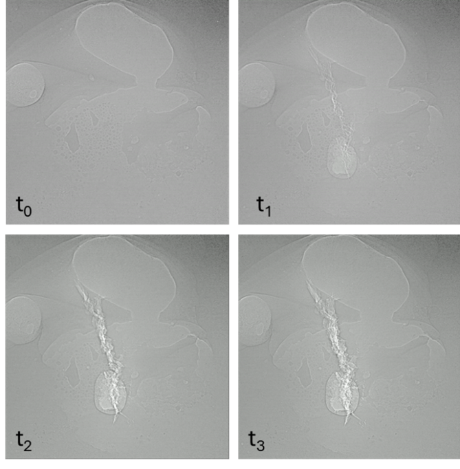
The first in-situ radiographic observations of laser processing with this setup were performed to observe solidification crack formation (Fig. 3). The frames show the location and the formation of the solidification crack as well as its opening during cooling and final state. This enables us to study the crack formation mechanism in addition to its final appearance. The setup also allows for low-frame-rate radiography to follow the formation of hydrogen- induced delayed cracks, which can sometimes require up to 30-60 minutes to reach their full extent of propagation.
Diffractometric measurements for phase and stress analysis
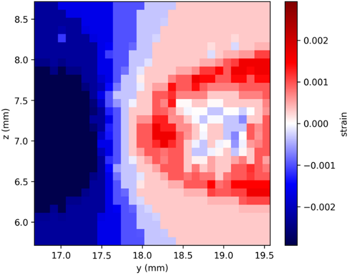
Using this system, it is also possible to derive diffraction results. Those can be helpful, e.g., to analyze phase transformations and the development of residual stresses during cooling after laser treatment. This enables the analysis of the temporal development of microstructure in addition to analyzing the final state. In our case, diffraction was used to record strain maps (Fig. 4), which gave indications as to where cracks might occur, the critical stress level required to initiate a crack, and how the material relaxes after a crack appeared.
Accessibility support
If you are interested in using the laser and axle system at the Swedish Materials Science beamline, please contact Denise McCluskey (denmccl@ kth.se) for more information.