
Professor Martin Bache from the Rolls Royce University Technology Centre – College of Engineering discusses the growing technology additive layer manufacturing and how it is shaping the industrial sector.
Additive layer manufacturing (ALM) is a rapidly growing technology receiving widespread attention from a multitude of industrial sectors for component repair and manufacture. The layer-by-layer process has evolved significantly over the past couple of decades and is now capable of fabricating near net shape, fully dense structural parts via two distinct routes: blown-powder (BP) or powder-bed (PB) manufacturing. BP has found use in repair scenarios for advanced, aero-gas turbine bladed disk components, otherwise referred to as ‘blisks’, where a complete overhaul of the part could be costly and timely, whereas additive repair could be performed in-situ. PB technologies, however, are more prominent in the manufacture of whole components. In 2015, a flying test bed A380 aircraft from Airbus provided a significant milestone in the world of ALM, demonstrating a Rolls-Royce Trent XWB-97 engine that was equipped with 48 aerofoil shaped vane components, each of which were produced by ALM.
The emergence of ALM is linked to the significant benefits that the process can offer, compared to more conventional manufacturing processes, such as forging or casting. These include considerable cost savings due to less material wastage, short lead times and improved buy-to-fly ratios, whilst also being capable of forming highly intricate components that would not be possible with more traditional methods.
Understanding the transient microstructures which are typically produced in ALM build material, which can lead to a significant variance in the mechanical properties across the component, is a fundamental research requirement. Furthermore, considering the multiple interactions of the intra and inter build process variables on the integrity and consistency of the final structure, traditional laboratory scale test approaches are deemed unsuitable for mechanical characterisation as it is difficult to extract representative test specimens which comply to the relevant International test standards.
In recognition of this issue, academics and researchers from the Rolls-Royce University Technology Centre (RRUTC) in Materials at Swansea University, have devoted significant effort in defining methodologies that can accurately define the mechanical characteristics of such complex materials. The RRUTC is based within the Institute of Structural Materials (ISM) at Swansea University’s new Bay Campus, and currently consists of a team of 6 academics supported by 15 research officers and a rolling cohort of over 30 postgraduate PhD or EngD students. The ISM is supported by Swansea Materials Research & Testing Ltd. (SMaRT), an ISO 17025 accredited commercial test facility that supplies design quality mechanical data to a range of companies within the structural material sector. From this group, a team of 6 scientists have formed under the supervision of Dr. Robert Lancaster working on related projects in unison with senior technologists and engineers from Rolls-Royce plc.
One approach adopted by the team to characterise these 3D build geometries is small scale testing, which can provide a discrete means of attaining mechanical property information from materials of limited dimensions. One such technique is the small punch (SP) test where miniature disc specimens can be extracted in a variety of orientations from the build to evaluate the anisotropic nature of the part, thus providing important, localised data.
The SP test is a miniaturised mechanical test method that has previously been employed to evaluate neutron irradiation damage in nuclear reactor materials and for remnant life assessment of power plant components extracted from operation. The primary advantage of this approach relates to the small volume of test material required, such that the test technique has been employed across laboratories worldwide to obtain creep rupture lives and tensile fracture data on a wide variety of different material systems. SP also offers the ability to correlate test data generated through such methods to those produced from more conventional approaches, making the test methodology a practical and attractive solution for many geometry related issues where material characterisation is required. Much research has now been published by the Swansea led collaborative team on materials ranging from single crystal superalloys for high pressure turbine blade applications, titanium alloys for fan blades and intermetallic titanium aluminides for low pressure turbine blade components. With this knowledge, the SP test is now being employed to assess the properties of additive layer structures.
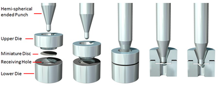
The test typically comprises of a round miniature disc specimen, 9.5mm in diameter and 0.5mm in thickness, which is clamped between a die set, from which a load is exerted onto the top surface through a hemi-spherical ended punch. From here, depending on whether the load is applied under constant displacement or constant load, a representative tensile or creep curve is produced.
The results are comparable to more conventional test approaches, particularly the SP creep test which typically exhibits the classical 3 stages of deformation, which are widely recognised from uniaxial experiments. A European Code of Practise for Small Punch testing was formulated in 2009 to ensure consistency across multiple international test houses and institutions, from which a creep correlation factor, or the kSP factor, was proposed, where the SP load may be correlated to a uniaxial creep stress in order to compare SP and conventional creep data. This method has found widespread success in a number of material systems and is now widely accepted.
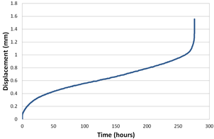
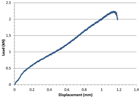
Figure 3. SP curves for a nominal PB nickel alloy showing (a) creep behaviour and, (b) tensile response
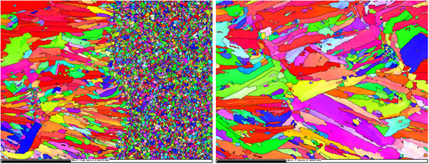
Given the transient and anisotropic nature of the microstructure in ALM structures, SP specimens can sample isolated regions of interest and reveal any variance in the properties across the build. Naturally, this is of high importance in the design of ALM components, helping to identify regions susceptible to a variation in properties, information that is impossible to gain from more conventional, larger scale mechanical test approaches.
References
1. R.C. Hurst, R.J. Lancaster, S.P. Jeffs, M.R. Bache “The contribution of small punch testing towards the development of materials for aero-engine applications”. Theoretical and Applied Fracture Mechanics (2016) 10.1016/j.tafmec.2016.07.013
2. R.J. Lancaster, G.R. Davies, H.W. Illsley, S.P. Jeffs, G.J. Baxter “Structural Integrity of an Electron Beam Melted Titanium Alloy”. Materials 9(6) (2016) 10.3390/ma9060470
Professor Martin Bache
Director – Rolls-Royce UTC in Materials
Director – Institute of Structural Materials
The Rolls Royce University Technology Centre – College of Engineering
Please note: this is a commercial profile


