
Dr Carlos Ziebert, Head of IAM-AWP’s Calorimeter Center at the KIT, explains how heat flux sensors help in advancing thermal management
Established in 2011, the Calorimeter Center at the Karlsruhe Institute of Technology’s (KIT) Institute for Applied Materials – Applied Materials Physics, operates Europe’s largest battery calorimeter laboratory. It provides six Accelerating Rate Calorimeters (ARCs) of different sizes – from coin to large pouch or prismatic automotive format, which allow the evaluation of thermodynamic, thermal and safety data for Lithium-ion (or Li-ion battery) and post-Lithium batteries on material, cell and pack level for both normal and abuse conditions (thermal, electrical, mechanical). However, such a sophisticated calorimeter is not needed for all measurement types. Important thermal data can already be collected by a small heat flux sensor (HFS).
Measurements with a HFS
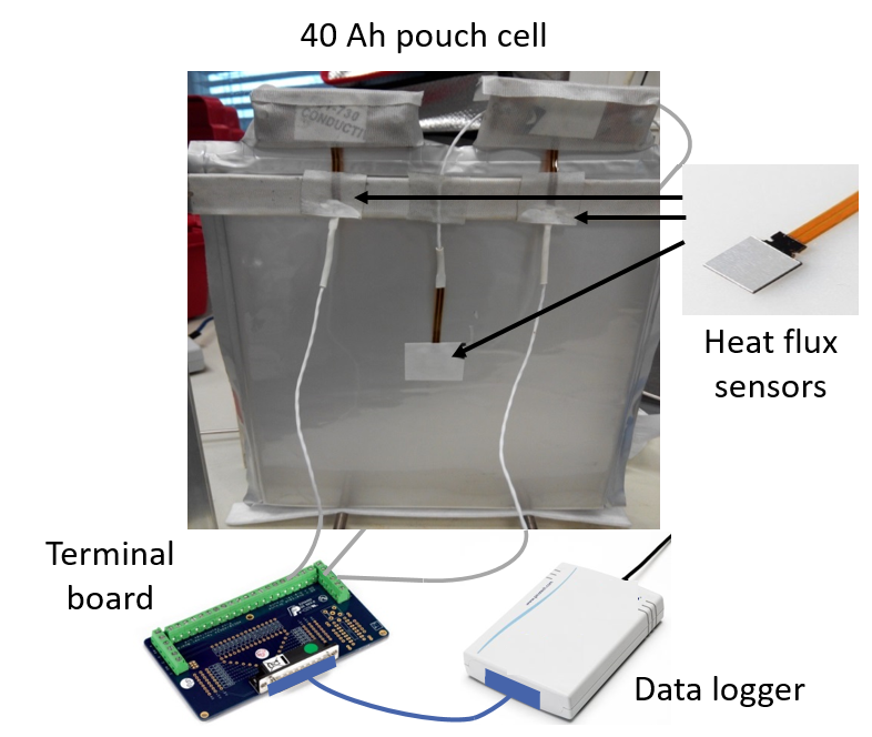
The thermal management of Li-ion batteries is becoming more and more important with increasing energy density because an uncontrollable increase in temperature (so-called thermal runaway) can cause an ignition or even explosion of the cell with a simultaneous release of toxic gases. In order to adapt the thermal management system to the individual needs of the cells, quantitative data of the thermal parameters are needed. It will be shown how heat flux sensors can be used to provide: i) Values for the specific heat capacity; ii) Heat transfer coefficients for the different sides of a cell and; iii) Values for the generated heat. A thermopile based Heat Flux Sensor is composed of tiny, serially connected semiconductor piles sandwiched between two flat surfaces, forming the sensor. Any heat flux passing through the sensor creates a temperature difference due to the Seebeck effect, which produces a voltage difference proportional to the heat passing through the surface. This voltage difference on different areas of a Lithium-ion cell is read out using a data logger, which is attached to a terminal board connecting the wires coming from the sensors (see Fig. 1). Depending on the sensor’s sensitivity, the resulting values are converted into heat flux. A HFS can detect all three possible types of heat transfer: convection, conduction and radiation.
Effective specific heat capacity
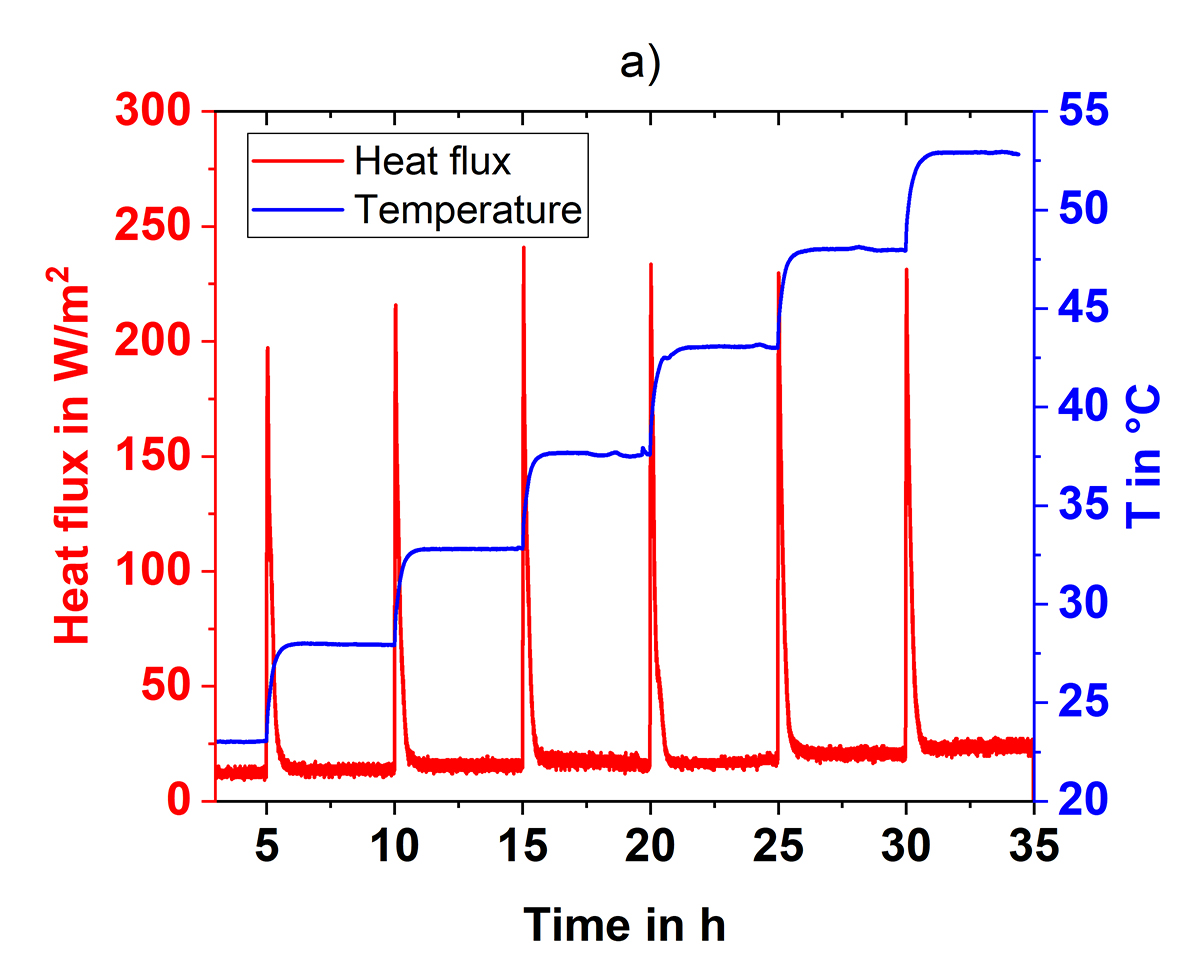
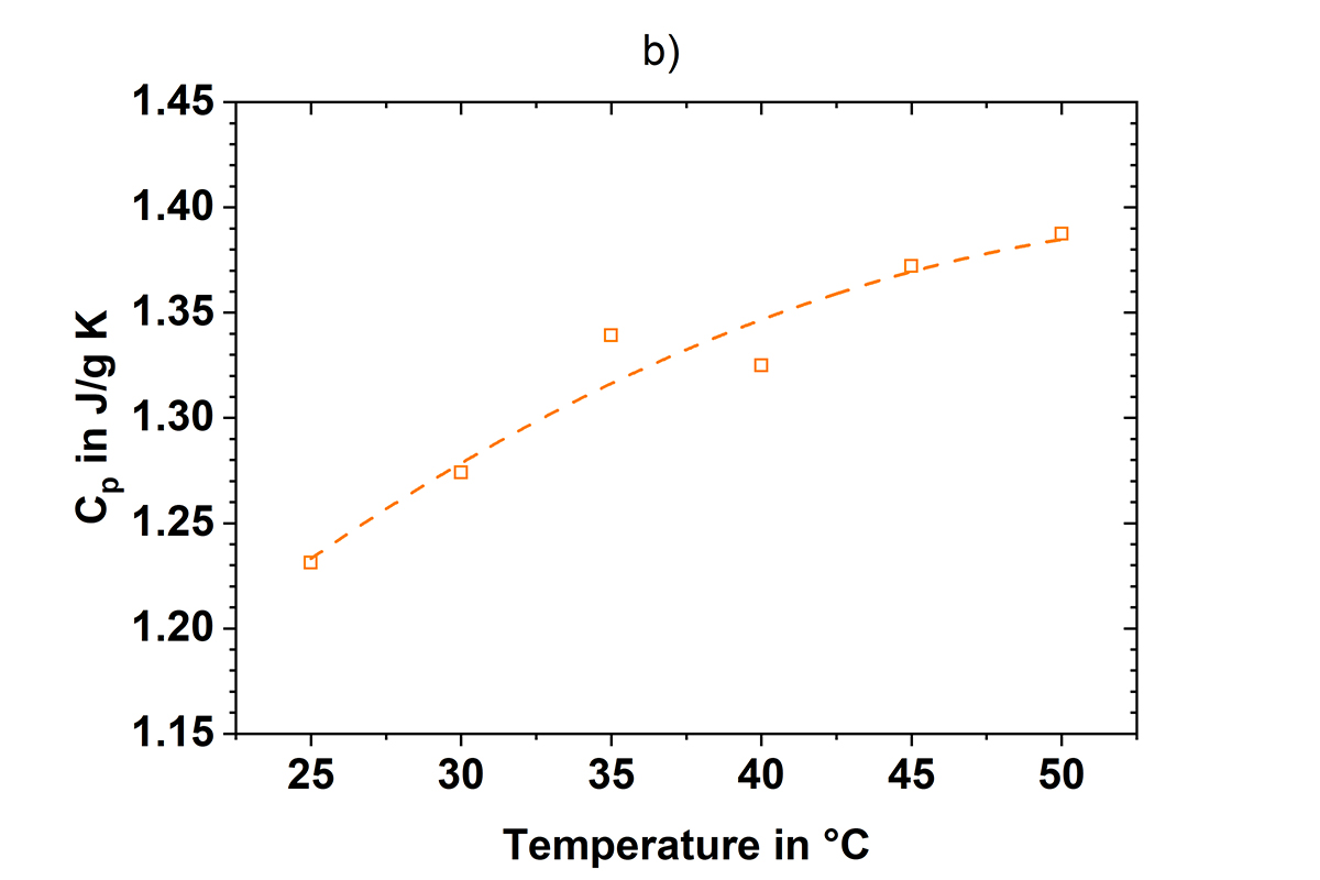
To measure the effective specific heat capacity Cp of a Lithium-ion cell, a HFS is attached on its surface and the heat flux response and a series of temperature steps are recorded, as shown in Fig. 2a). Integration of the peak areas and division by the cell mass gives the effective specific heat as a function of temperature (s. Fig. 2b)).
Heat transfer coefficient (HTC)
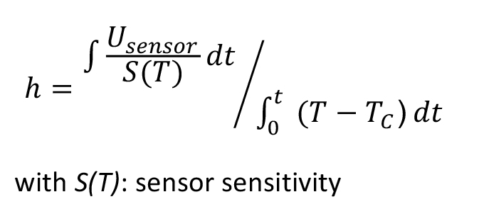
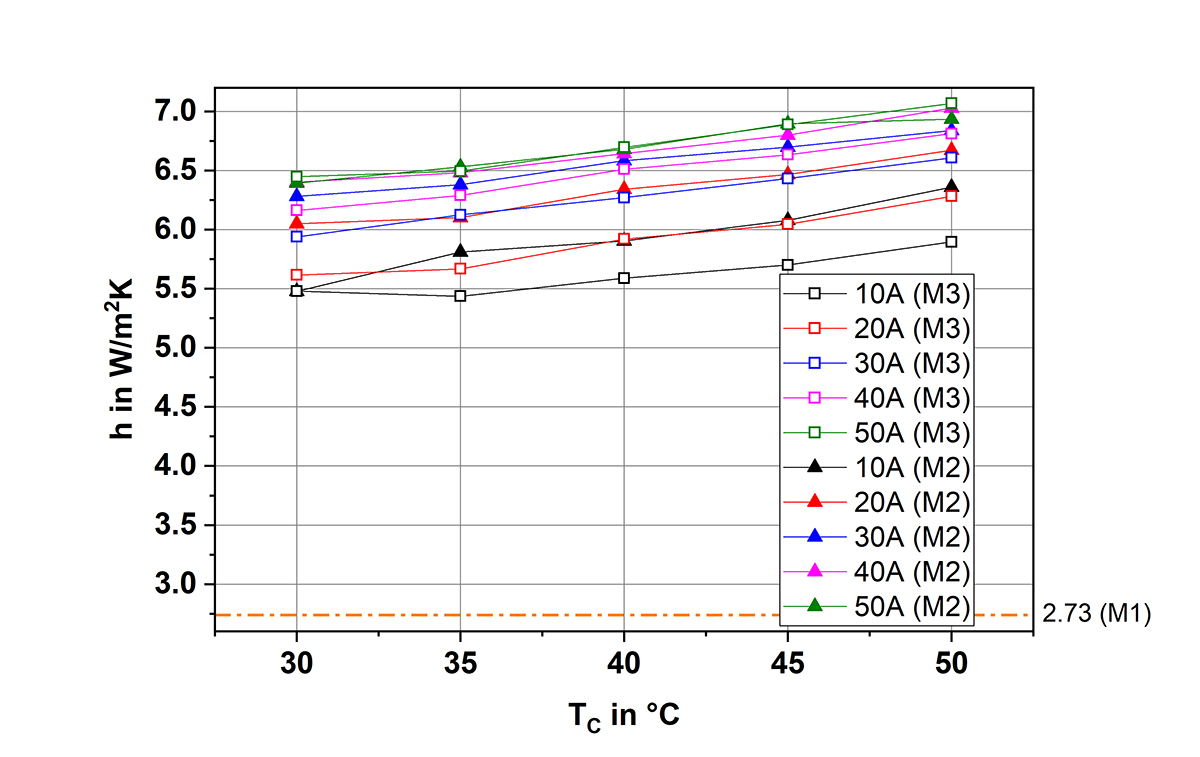
The heat transfer coefficient (HTC) h is another important parameter, that can be measured using a HFS. It is given as the quotient between the area of the sensor signal during the cycling of a cell and the area of a thermocouple signal at the same place:
In Fig. 3, it can be clearly seen that the HTC is determined by the classical dummy method (M1) differs a lot from the one determined by a HFS (M3). In the dummy method, the heaters in the calorimeter chamber heat up a dummy, made from an Al alloy with similar mass and dimensions as the cell, stepwise. The HTC is determined from the slope of the curve of the temperature difference between the dummy and its surroundings vs. the time. Obviously, this situation differs from a Lithium-ion cell where the heat is generated from inside. However, there is a very good agreement between the HFS values (M3) and the values from M2, which are derived from an exponential fitting to the cooling curve after switching off the current. In addition, the HFS method allows measuring the HTC simultaneously as a function of temperature and applied charge/discharge current.
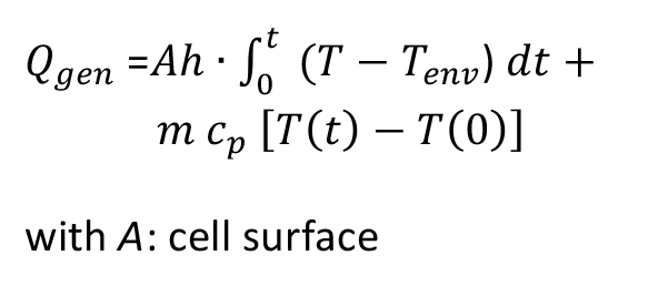
Generated heat
After the determination of the Cp value and the HTC, the temperature data that are recorded by thermocouples attached to the cell surface can be converted to the generated heat to determine cooling requirements for the thermal management system:
Thus, heat flux sensors can determine many parameters that are of the utmost importance for the thermal management of cells. Moreover, they can be applied in the same way on the pack level by attaching them to different positions within the pack.
We hope that our research will help the European Battery Industry to make further progress in the field of thermal management.
Please note: This is a commercial profile


