
Associate Professor Marco Beleggia from the Technical University of Denmark, explains to us how to refocus spin structures with Lorentz transmission electron microscopy
Manipulating the electron spin for the purpose of using it as information carrier is at the basis of the field of research called spintronics. Compared to electronics, where it is the electron charge that carries information, these new materials bring the promise of faster (higher frequency operation) and more sustainable (lower power consumption) technologies in our daily life.
Exotic spin configurations such as homochiral Néel walls[1] and skyrmions[2] have garnered intense interest recently as basic building blocks of next-generation magnetic-based memory, logic and sensors[3]. These structures are formed when the various driving forces in play find an equilibrium: exchange interaction favours alignment of neighbouring spins, anisotropy favours alignment along specific directions, demagnetization favours configurations that minimise stray fields and the Dzyaloshinskii-Moriya interaction (DMI) favours spins at right angles. The sign of the DMI determines whether the right-hand or the left-hand rule applies in choosing which perpendicular, hence the connection with chirality.
In magnetic materials where the preferred direction of magnetization is orthogonal to the plane of the film and where DMI plays a role, the exchange and DMI energy terms favour Bloch and Néel walls, respectively, while minimisation of stray fields leads to flux-closed configurations akin to a toroidal solenoid. The competition between these energies leads to complex domain walls that cannot be described as fully Bloch or Néel[4] and plays an essential role in their dynamical response to applied fields and currents. Understanding this balance is crucial for the development of spintronic devices based on chiral domain walls.
The first step in learning how to control spin structures is to visualise them, observe how they respond to external stimuli and assess the relative strength of the various energy terms. Several magnetic imaging techniques are available for this purpose. For example, X-ray resonant magnetic scattering, nitrogen-vacancy magnetometry and spin-polarized scanning tunneling microscopy. However, most techniques are restricted to deduce the domain wall structure from surface states and due to spatial resolution limitations, often fail to measure precisely the wall width, which would provide access to the strength of the exchange energy.
A technique called Lorentz transmission electron microscopy (LTEM) is a classic tool to study magnetism[5]. It has been successfully applied to understand the local spin order in materials that host skyrmions[2] and other chiral spin structures. LTEM is based on the deflection that electrons experience as they traverse a magnetic sample as a result of the Lorentz force. Since beam electrons fly past a sample at near-light speed, these deflections are tiny. To have any chance of measuring an effect, we need to allow the deflected electrons to travel a large distance by moving the detector well below the sample and take a picture of them only then. This is the concept of “defocus”: the more out of focus we are, the more contrast we have in the image. However, as anyone who has taken a badly focused picture with a standard camera can confirm, a defocused image is blurred to the point where the features we want to capture are no longer discernible. This is the conundrum of LTEM, we add defocus because without it we see nothing but the more defocus we add, the less clearly we see the features we are interested in.
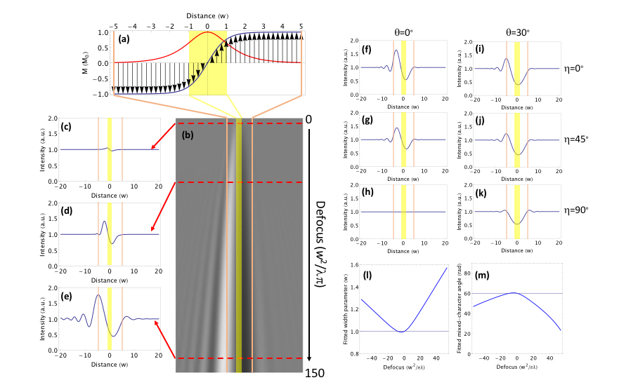
The key finding in this article is a recipe for data analysis that takes as input a set of heavily blurred defocus images of a hybrid Bloch/Néel domain wall, where the wall appears enlarged and η may appear under- or over-estimated and produces as output the “true” values of the domain wall width and the mixed-character angle. This new algorithm relies on image simulations carried out with the full Fresnel propagator in a wave-optical framework that includes interference and diffraction effects. As a result, we are no longer forced to choose between images that are either blurry and contrasted (large defocus) or sharp but noisy (small defocus). We have learned how to refocus spin structures with LTEM.
Please note: This is a commercial profile
References
- M. Bode, M. Heide, K. Von Bergmann, P. Ferriani, S. Heinze, G. Bihlmayer, A. Kubetzka, O. Pietzsch, S. Blügel, R. Wiesendanger. Nature 447, 190 (2007).
- A. Tonomura, X. Yu, K. Yanagisawa, T. Matsuda, Y. Onose, N. Kanazawa, H.S. Park, Y. Tokura. Nano Lett. 12, 1673 (2012).
- W. Jiang, G. Chen, K. Liu, J. Zang, S.G.E. te Velthuis, A. Hoffmann. Phys. Rep. 704, 1 (2017).
- Y. Dovzhenko, F. Casola, S. Schlotter, T.X. Zhou, F. Büttner, R.L. Walsworth, G.S.D. Beach, A. Yacoby. Nat. Commun. 9, 2712 (2018).
- J.N. Chapman. J. Phys. D: Appl. Phys. 17, 623 (1984).
- J.A. Garlow, S.D. Pollard, M. Beleggia, T. Dutta, H. Yang, Y. Zhu. Phys. Rev. Lett. 122, 237201 (2019).


