
Here we find out how the Giantleap project improves the automation of non-polluting transportation with the lifetime extension of PEM fuel cells
City buses have long been considered an early market for the introduction of fuel cells, since a large deployment of FC buses is able to economically sustain its own hydrogen-refuelling infrastructure.
Several demonstration projects have shown the feasibility of fuel cell buses, in particular, the long-running CHIC project. However, experience has also shown that the availability and reliability of fuel cell buses are not mature yet. The project Giantleap addresses this challenge by improving the lifetime and reliability and reducing the TCO of fuel cell systems in city buses. This is achieved through an advanced control system that includes novel diagnosis and prognosis approaches: The system is, therefore, able to avoid faults and mitigate degradation.
Consortium: Three research institutions SINTEF, UFC, FESB and two OEM (BEG, EK) and one end-user (VDL-ETS) have put effort towards the realisation of the prototype – see the Giantleap Team.
Budget: €3.26 million, May 2016 – October 2019, TRL increase from 3 to 7.
Funding: Giantleap has received funding from the fuel cells and hydrogen two joint undertaking under grant agreement no. 700101. This joint undertaking receives support from the European Union Horizon 2020 research and innovation programme and Hydrogen Europe and N.Erghy.
Diagnosis of Automotive PEMFC
Degradation of automotive fuel cells (FC) was studied through a series of accelerated stress tests with different laboratory diagnostic methods such as polarization curves, electrochemical impedance spectroscopy, cyclic voltammetry and linear sweep voltammetry. The single fuel cell provided by EK, with the same MEA configuration as in the delivered stacks, has shown excellent performance and a low degradation rate. In order to investigate a phenomenon of recoverable performance degradation, the impact of different shutdown procedures and durations of the intentional recovery periods were also tested. The shutdown procedure without nitrogen purge proved to be the most effective for performance recovery, while the prolonged soak time reduces the recovery effect. Low-frequency intercept in the impedance spectrum (ELFIS) has been identified as a suitable indicator of both catalyst degradation and recovery effect that can be used to monitor the FC’s state of health. In collaboration with SINTEF, a method of quick and simple measurement of this parameter has been developed and applied in the system.
Prognosis of Automotive PEMFC Systems
The prediction of the FC ageing and its interaction with the balance of plant (BoP) is considered as a strategical approach to anticipate and consequently reduce the FC system degradation. A PEMFC system model has been developed using the Energetic Macroscopic Representation (EMR) formalism. (EMR is a multi-physics graphic model approach used to simulate complex systems organisation in correlated subsystems; where the connections are based on physical causality principals.) The model integrates stack and BoP ageing laws and is adapted for on-board prognostics and health management (PHM) purposes. A voltage decay is observed with ageing, and its trend is analysed and confronted with the observed long-term testing results. The BoP sub-system includes the hydrogen line, the airline and cooling system. The operation of the stack was remarkable. It showed very low degradation level in different operating conditions including some transient failures in the coolant circuit.
Control & Health Management of PEMFC System
The Fuel Cell Control Unit (FCCU) is provided by BEG and handles all measurements and actuating devices for the complete FC system including the stacks, hydrogen storage, all the necessary BoP components, external communication with the bus system and operator interaction. The control system ensures that the FC and other BoP components are always kept within safe operating conditions from startup to shut-down and during normal operation modes when the FC delivers charging power to the bus. All measured parameters can be logged and made available for offline analysis. In addition to normal power delivery modes, the system can run specific functions for measuring parameters that are of interest for health performance monitoring. This includes the polarization curve and low- frequency EIS intercept.
PEM Stack module for Range Extender
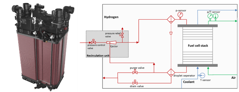
The requirements towards a fuel cell for bus application significantly differ from those in the passenger car segment. With buses, the lifetime requirement of 20,000 operating hours in ten years and even more considerably exceed those of passenger cars, which require a lifetime of about 6,000 hours. The FC as a central element in the system must be composed of parts fulfilling these requirements. ElringKlinger as the responsible partner for stack development provided full-size stack modules for laboratory experiments and for the integration into the FC range-extender bus system. The NM5 stack platform suitable for mass production which is used in this project offers the possibility of realising highly efficient systems due to a very low-pressure drop on the cathode side. Patented structures within the metallic bipolar plate ensure a very homogeneous gas distribution and, therefore, operational stability especially in partial load at lower gas flow rates. Besides sensors, valves, droplet separators and bypass structures, it is also worth noting that the passive hydrogen recirculation unit as a major part of the anode sub-system is already integrated into the stack module. With hydrogen gas recirculation, in general, it is important to maintain optimal gas distribution, as well as humidification of the dry hydrogen supplied by the tank system of the trailer.
System design & Balance of Plant A robust FC system including a reliable control was designed by Bosch Engineering. This system was assembled, tested on testbench at BEG facilities before it was delivered for integration and operation into the range extender in a demonstration prototype trailer at VDL-ETS facilities and on-road.
FC control unit system includes the control unit, the accompanying software and a reliable telematics data recording system specified and developed as a basis for data evaluation from the operating range extender. Several enhanced control functionalities were implemented to observe the SOH and reduce degradation. The FCCU performance was validated based on the range extender system testing.
System design & interfaces After subsystem interfaces clarification, i.e. mechanical, electrical, heat and communication interfaces, the entire FC system design was specified. Applicable norms for type approval were also considered in the definition of the architecture.
BoP Components were selected considering their robustness and expected lifetime, in particular, the three main components that cause most system failures or have a large impact on its cost, i.e. air supply unit, pressure reducer and the cathode inlet humidifier. The system performance and the applicability and relevance of the advanced control algorithms for the durability of new and future FC applications were demonstrated.
Hydrogen Range Extender for Heavy Duty ZE Transport
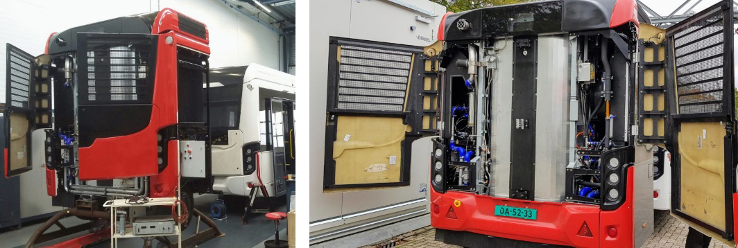
VDL-ETS has facilitated and developed the mobile test platform for ageing tests. The mobile platform has been built as a trailer, connected to an electrically driven VDL E-powered bus. This trailer has been equipped with vehicle lighting and brake system for safe operation during testing. All electrical connections for power supply, communication and high voltage have been provided. For software interfacing, VDL-ETS assisted BEG and EK in this communication for the safe start-up and shut down of the system and linking signals to the vehicle. During driving with the bus trailer combination, VDL-ETS collected the measuring data, which is useful and available for all the calculations done by the partners.
After 3½ years, Giantleap has been concluded on a prototype demonstration in the operational environment (i.e. on road, TRL 7) as opposed to the originally planned relevant environment (i.e. in a laboratory test bench, TRL 6). The bus and its range extender have experienced several test-driving around VDL-ETS’s premises in Valkenswaard (Netherland). One remarkable result is the resilience of ElringKlinger’s stacks: even after being subjected to a failure in the coolant circuit that caused some cells to overheat, the stack performed as nothing had happened after the error had been corrected. ElringKlinger’s stack actually overperformed in the system compared to their nominal specifications.
BEG has strengthened their activities in FC systems and now offer BoP components specifically for such systems. While the project has been running, VDL-ETS has become the world’s largest zero-emission bus manufacturer (outside of China), though most of these are battery buses. Electric buses have now surpassed diesel buses in reliability (96.2% against 96.0%), and over 90% of VDL-ETS’s bus sales today are zero-emission. As the project concluded, the prototype developed in Giantleap has already evolved in a new generation ready to be demonstrated in passenger long-haul service between Rotterdam and Zeeland within the project 3-Emotion.![]()
![]()
Several public reports and open-access publications have been released: evaluations of diagnostics; prognostics; testing and control performance; an assessment of the business case for hydrogen buses from bus operators’ perspective; a quantitative evaluation of Giantleap’s ability to reach its targets; and a complete database of all publishable data produced during the project.
Please note: This is a commercial profile


